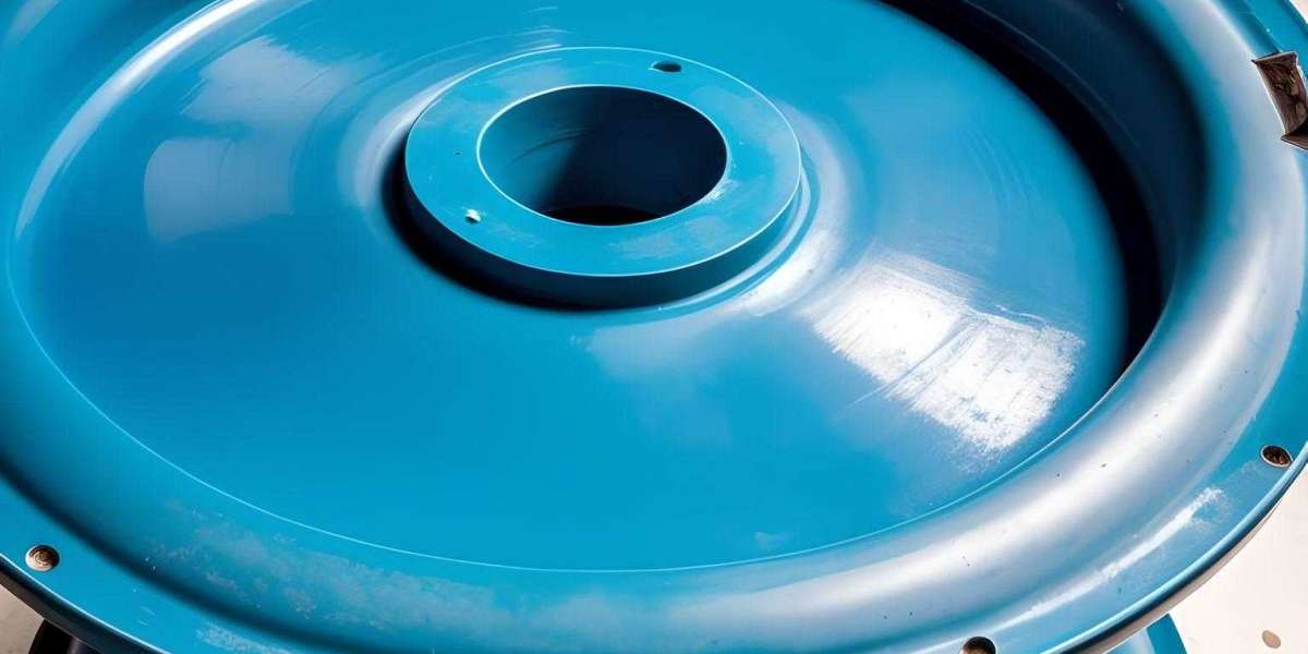
A robust ejection system is crucial for any plastic injection or compression mold to ensure complete, damage-free part removal after every cycle. Optimized ejection mechanisms are needed to avoid common issues like parts sticking in mold, scratching, warpage, and mold damage over prolonged use. This guide covers the fundamentals of analyzing and designing part ejection systems for molds.
What is Part Ejection in Plastic Molds?
Part ejection refers to the mechanisms built into a mold to remove solidified plastic parts off core and cavity surfaces after mold opening.
Dedicated ejector pins, sleeves, blades and stripper plates are actuated to push parts off molding surfaces without damaging fragile mold details or sticking to surfaces. Controlled application of ejection force is critical.
A mold can have dozens of ejector pins, bars and plates integrated into the tool depending on part geometry. Precisely engineered ejection is crucial for repetitive trouble-free mold operation.
Importance of Smooth Ejection
Effective part ejection provides the following benefits:
- Maximizes mold up-time and productivity
- Avoids part damage during demolding
- Lowers ejection forces, reducing mold wear
- Allows faster cycling without sticking parts
- Prevents buildup of residual stress in parts
- Eliminates need for operators to manually remove parts
Proper ejection design greatly improves reliability and performance of production molds.
Types of Ejection Systems
There are three main types of part ejection systems used in plastic molds:
Pin Ejection
Individual tapered pins push parts off deep pockets in core/cavity. Most commonly used system. Pin diameter, length, angle and stroke are important.
Sleeve Ejection
Hollow sleeves surround sections and eject parts off cylindrical/square cores. Provides balanced ejection.
Blade/Stripper Plate Ejection
Thin blades or stripper plates eject shallow/flat parts off cavity surfaces. Large plates can eject multiple parts in one stroke.
Molds typically use a combination of pins, sleeves and blades placed strategically for smooth demolding based on part geometry.
Key Factors Affecting Ejection
Several factors must be analyzed to design an effective ejection system:
- Draft angles: Draft on vertical walls provides a release angle for ejection. Insufficient draft can prevent part release.
- Surface finish: Glossy/mirror surfaces increase demolding friction and require high ejection forces.
- Undercuts: Severe undercuts lock parts in the mold, blocking ejection.
- Part thickness: Thick sections cool and shrink onto cores tightly. Graduated ejectors may be needed.
- Material: Thermoplastic properties like hardness, elasticity, friction affect demolding behavior.
By considering these elements, optimal ejection systems can be designed.
Ejection Design Guidelines
Here are some general design guidelines for reliable part ejection from molds:
- Analyze part geometry to position ejectors for balanced removal force
- Use multiple smaller diameter pins rather than few large pins
- Locate ejector pins close to part contours to minimize deflection
- Design pins/sleeves to eject in direction opposite of part shrinkage
- Place assembly taper on pins for easier mold machining
- Allow adequate pin protrusion above mold core/cavity surface
- Angle ejector pins along draft angles for clean release
- Specify hard chrome plated pins to minimize friction and wear
- Provide sufficient ejector stroke for complete demolding
- Use concentric sleeves to eject hollow or cylindrical cores
Proper ejector layout as per these rules prevents issues and damage during part removal from the mold.
Ejection Design Optimizations
Some advanced design optimizations for ejection systems include:
- Using programmable electric servo ejectors for computer controlled precision
- Having independent ejector drives for sequential ejection
- Integrating air pops or assisted air ejection at problem zones
- Designing floating stripper plates that follow part geometry
- Using active release coatings on core/cavity to reduce ejection forces
- Specifying optimized surface finishes on ejectors for friction control
- Providing adjustable stroke ejector pins to fine-tune ejection
- Having independent shutoffs/sequence blocks for staged opening
These enhancements customized to mold requirements result in the most effective and reliable ejection performance. Proper mold design is critical.
Ejection Troubleshooting
Some common ejection issues and remedies:
Parts Sticking: Increase draft angles, reduce surface gloss, use active coatings
Short Shots: Improve venting, increase injection pressure, raise mold temperature
Deformed Parts: Balance ejection forces, reduce pin size, change material
Flashing: Improve alignment and shutoffs, increase clamping force
Scratched Parts: Re-locate/re-size ejector pins, improve surface finish
Non-uniform removal: Balance pin layout, use multiple smaller pins
With careful observation and design tweaks, ejection systems can be optimized for smooth demolding.
Conclusion
Robust ejection design is a must for trouble-free mold operation. Following fundamental ejection design principles coupled with analysis and simulations ensures parts can be removed reliably without sticking or damage.


